Product Description
CHINAMFG TEC Product Description:
| Material | Carbon Steel | SAE1571, SAE1045, Cr12, 40Cr, Y15Pb, 1214Letc | |
| Alloy Steel | 20CrMnTi, 16MnCr5, 20CrMnMo, 41CrMo, 17CrNiMo5etc | ||
| Brass/Bronze | HPb59-1, H70, CuZn39Pb2, CuZn40Pb2, C38000, CuZn40etc | ||
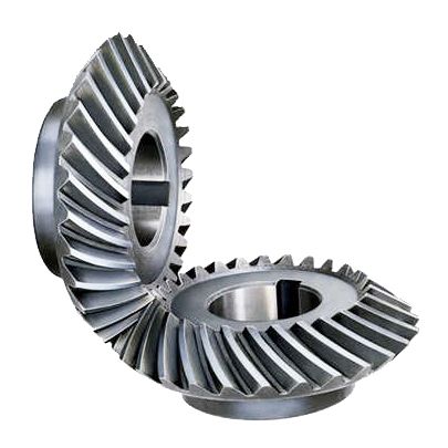
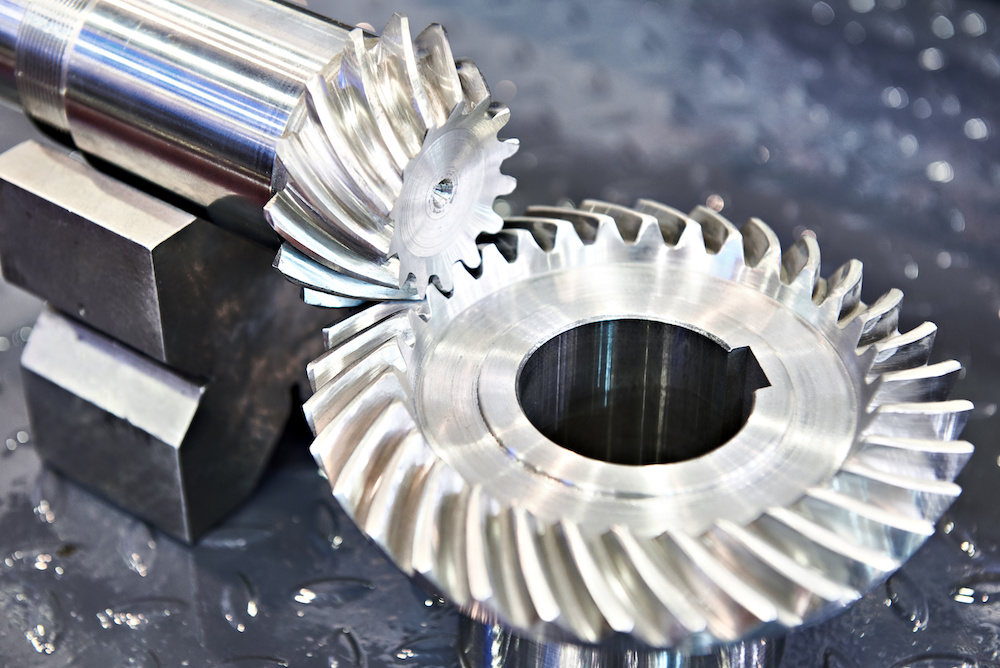
| Type | OEM ODM Hign Quality Spiral Bevel Gear | ||
| Treatment | Heat treatments, Carburizing, Polishing | ||
| Standard | ISO /R 606 | ||
| Machining process | fabrication,stamping,deep drawing,gear hobbing, gear milling, gear shaping, machining and assembly gear broaching, gear grinding and gear gaping | ||
| Module | 1.0, 1.25, 1.5, 1.75, 2.0, 2.25, 2.5….8.0 etc | ||
| Tolerance control | Outer Diameter:±0.005mm | Length Dimension:±0.05 mm | |
| Teeth accuracy | GB1244-85, DIN8188, ISO/R 606 , ANSI B 29.1M | ||
| Heat treatment | Quenching & Tempering, Carburizing & Quenching, High-frequency Hardening, Carbonitriding… | ||
| Surface treatment | Blacking, Polishing, Anodization, Chrome plating, Zinc plating, Nickel plating… | ||
| FAQ: |
| Main Markets | North America, South America, Eastern Europe , West Europe , North Europe, South Europe, Asia |
| How to order? | * You send us drawing or sample |
| * We carry through project assessment | |
| * We give you our design for your confirmation | |
| * We make the sample and send it to you after you confirmed our design | |
| * You confirm the sample then place an order and pay us 30% deposit | |
| * We start producing | |
| * When the goods is done, you pay us the balance after you confirmed pictures or tracking numbers. |
| Packaging and Delivery time: | |
| Packaging | Polyethylene bag or oil paper for each item; |
| Pile on carton or as customer’s demand | |
| Delivery of Samples | By DHL, Fedex, UPS, TNT, EMS |
| Lead time | 10-15 working days as usual, 30days in busy season, it will based on the detailed order quantity. |
| Application: | Motor, Electric Cars, Motorcycle, Machinery, Marine, Agricultural Machinery, Car |
|---|---|
| Hardness: | Hardened |
| Manufacturing Method: | Cast/Cut/Rolling/Sintered Gear |
| Toothed Portion Shape: | Spur/Bevel/Curved/Doublehlical Gear |
| Material: | Stainless Steel |
| Type: | Circular/Wormand Worm Wheel/Bevel/Non-Circular/Rac |
| Samples: |
US$ 10/Piece
1 Piece(Min.Order) | |
|---|
| Customization: |
Available
| Customized Request |
|---|

Can bevel gears be used in precision manufacturing equipment?
Yes, bevel gears can be used in precision manufacturing equipment due to their ability to transmit motion and power at varied angles with high accuracy. Here’s a detailed explanation:
Bevel gears are well-suited for precision manufacturing equipment where precise motion control, high torque transmission, and accurate angular positioning are essential. Here are some key reasons why bevel gears are suitable for such applications:
- Angular Transmission: Bevel gears excel at transmitting motion and power between intersecting shafts at different angles. In precision manufacturing equipment, where components often require precise angular positioning, bevel gears provide an efficient means of achieving the necessary motion transfer. They allow for smooth and accurate rotation, ensuring precise alignment and positioning of machine components.
- Compact Design: Bevel gears have a compact design, making them suitable for applications where space is limited. In precision manufacturing equipment, where machines often have complex structures and require tight integration of components, the compact size of bevel gears allows for efficient utilization of available space. This is particularly advantageous when designing compact and high-precision machinery.
- High Torque Transmission: Bevel gears are capable of transmitting high torque loads, making them suitable for precision manufacturing equipment that requires the transmission of substantial power. Whether it’s in rotary tables, indexing mechanisms, or gearboxes, bevel gears can efficiently transfer high torque while maintaining accuracy and precision in motion control.
- Accuracy and Backlash Control: In precision manufacturing equipment, minimizing backlash and ensuring accurate motion control are critical. Bevel gears can be manufactured with high precision to achieve tight tolerances and minimal backlash. This allows for precise positioning, accurate motion control, and repeatable performance, which are essential in precision manufacturing processes.
- Customization Options: Bevel gears can be customized to meet specific requirements of precision manufacturing equipment. Different tooth profiles, gear ratios, materials, and surface treatments can be employed to optimize the gear performance for specific applications. This customization capability allows gear engineers to design bevel gears that precisely match the needs and specifications of the equipment.
Examples of precision manufacturing equipment where bevel gears are commonly used include CNC machines, milling machines, gear hobbing machines, rotary tables, indexing mechanisms, and various types of gearboxes. These machines rely on the precise and reliable motion transmission provided by bevel gears to achieve accurate and high-quality manufacturing processes.
It is important to note that the selection and design of bevel gears for precision manufacturing equipment should consider factors such as load requirements, speed, operating conditions, backlash limitations, and noise considerations. Gear engineers and machine designers often conduct detailed analyses and calculations to ensure the bevel gears meet the necessary performance criteria and contribute to the overall precision and reliability of the equipment.
In summary, bevel gears are well-suited for precision manufacturing equipment due to their ability to provide accurate angular transmission, compact design, high torque transmission, and customization options. Incorporating bevel gears in precision machinery contributes to precise motion control, accurate positioning, and reliable performance, enabling the production of high-quality and precise manufactured components.

How do you calculate the efficiency of a bevel gear?
To calculate the efficiency of a bevel gear, you need to compare the power input to the gear with the power output and account for any losses in the gear system. Here’s a detailed explanation of the calculation process:
The efficiency of a bevel gear can be calculated using the following formula:
Efficiency = (Power output / Power input) x 100%
Here’s a step-by-step breakdown of the calculation:
- Calculate the Power Input: Determine the power input to the bevel gear system. This can be obtained by multiplying the input torque (Tin) by the input angular velocity (ωin), using the formula:
- Calculate the Power Output: Determine the power output from the bevel gear system. This can be obtained by multiplying the output torque (Tout) by the output angular velocity (ωout), using the formula:
- Calculate the Efficiency: Divide the power output by the power input and multiply by 100% to obtain the efficiency:
Power input = Tin x ωin
Power output = Tout x ωout
Efficiency = (Power output / Power input) x 100%
The efficiency of a bevel gear represents the percentage of input power that is effectively transmitted to the output, considering losses due to factors such as friction, gear meshing, and lubrication. It is important to note that the efficiency of a bevel gear system can vary depending on various factors, including gear quality, alignment, lubrication condition, and operating conditions.
When calculating the efficiency, it is crucial to use consistent units for torque and angular velocity. Additionally, it’s important to ensure that the power input and output are measured at the same point in the gear system, typically at the input and output shafts.
Keep in mind that the calculated efficiency is an approximation and may not account for all the losses in the gear system. Factors such as bearing losses, windage losses, and other system-specific losses are not included in this basic efficiency calculation. Actual efficiency can vary based on the specific design and operating conditions of the bevel gear system.
By calculating the efficiency, engineers can evaluate the performance of a bevel gear and make informed decisions regarding gear selection, optimization, and system design.

How do bevel gears differ from other types of gears?
Bevel gears have distinct characteristics that set them apart from other types of gears. Here’s a detailed explanation of how bevel gears differ from other gears:
1. Tooth Geometry: Bevel gears have teeth cut on the cone-shaped surface of the gears, whereas other types of gears, such as spur gears and helical gears, have teeth cut on cylindrical surfaces. The tooth geometry of bevel gears allows them to accommodate intersecting shafts and transmit rotational motion at different angles.
2. Axis Orientation: Bevel gears have intersecting axes, meaning the shafts they are mounted on intersect each other. In contrast, other types of gears typically have parallel or skewed axes. The intersecting axis of bevel gears allows for changes in direction and allows for power transmission between shafts that are not in a straight line.
3. Types of Bevel Gears: Bevel gears come in different variations, including straight bevel gears, spiral bevel gears, and hypoid bevel gears. Straight bevel gears have straight-cut teeth and intersect at a 90-degree angle. Spiral bevel gears have curved teeth that are gradually cut along the gear surface, providing smoother engagement and reduced noise. Hypoid bevel gears have offset axes and are used when the intersecting shafts are non-parallel. Other types of gears, such as spur gears and helical gears, also have their own variations but do not typically involve intersecting axes.
4. Direction of Motion: Bevel gears can change the direction of rotational motion between intersecting shafts. Depending on the orientation of the gears, the direction of rotation can be reversed. This capability makes bevel gears suitable for applications where changes in direction are required. In contrast, other gears, such as spur gears and helical gears, transmit motion in a specific direction along parallel or skewed axes.
5. Load Distribution: Bevel gears distribute loads differently compared to other gears. Due to the conical shape of the gears, the contact area between the teeth changes as the gears rotate. This can result in varying load distribution along the gear teeth. Other gears, such as spur gears and helical gears, have a consistent load distribution along their teeth due to their cylindrical shape.
6. Applications: Bevel gears are commonly used in applications where changes in direction or speed of rotational motion are required, such as automotive differentials, marine propulsion systems, and power transmission systems. Other types of gears, such as spur gears and helical gears, are more commonly used in applications where parallel or skewed shafts are involved and changes in direction are not necessary.
While bevel gears have their unique characteristics, it’s important to note that different types of gears have their own advantages and applications. The selection of the appropriate gear type depends on factors such as the application requirements, operating conditions, space limitations, and load considerations.
In summary, bevel gears differ from other types of gears in terms of tooth geometry, axis orientation, types of variations available, direction of motion, load distribution, and applications. Their ability to accommodate intersecting shafts and change the direction of rotational motion makes them suitable for specific applications where other types of gears may not be as effective.


editor by CX 2023-09-15

Recent Comments