Product Description
K series Parallel Shaft-Helical Geared Motor Characteristics
1. Features:
- High efficiency: 92%-93%;
- Vertical output, compact structure, hard tooth surface , large output torque, low noise and long service life.
- High precision: the gear is made of high-quality alloy steel forging, carbonitriding and hardening treatment, grinding process to ensure high precision and stable running.
- High interchangeability: highly modular, serial design, strong versatility and interchangeability.
2. Technical parameters
| Ratio | 5.36-197.37 |
| Input power | 0.12-200KW |
| Output torque | 10-62800N.m |
| Output speed | 7-415rpm |
| Mounting type | Foot mounted, foot mounted with CHINAMFG shaft, output flange mounted, hollow shaft mounted, B5 flange mounted with hollow shaft, foot mounted with hollow shaft, B14 flange mounted with hollow shaft, foot mounted with splined hole, foot mounted with shrink disk, hollow shaft mounted with anti-torque arm. |
| Input Method | Flange input(AM), shaft input(AD), inline AC motor input, or AQA servo motor |
| Brake Release | HF-manual release(lock in the brake release position), HR-manual release(autom-atic braking position) |
| Thermistor | TF(Thermistor protection PTC thermisto) TH(Thermistor protection Bimetal swotch) |
| Mounting Position | M1, M2, M3, M4, M5, M6 |
| Type | K37-K157 |
| Output shaft dis. | 25mm, 30mm, 35mm, 40mm, 50mm, 60mm, 70mm, 90mm, 110mm, 120mm |
| Housing material | HT200 high-strength cast iron from R37,47,57,67,77,87 |
| Housing material | HT250 High strength cast iron from R97 107,137,147, 157,167,187 |
| Heat treatment technology | carbonitriding and hardening treatment |
| Single Stage Efficiency | up to 96% |
| Lubricant | VG220 |
| Protection Class | IP55, F class |
Starshine Drive
ZheJiang CHINAMFG Drive Co.,Ltd,the predecessor was a state-owned military mould enterprise, was established in 1965. CHINAMFG specializes in the complete power transmission solution for high-end equipment manufacturing industries based on the aim of “Platform Product, Application Design and Professional Service”.
CHINAMFG have a strong technical force with over 350 employees at present, including over 30 engineering technicians, 30 quality inspectors, covering an area of 80000 square CHINAMFG and kinds of advanced processing machines and testing equipments. We have a good foundation for the industry application development and service of high-end speed reducers & variators owning to the provincial engineering technology research center,the lab of gear speed reducers, and the base of modern R&D.
Our Team
Quality Control
Quality:Insist on Improvement,Strive for Excellence With the development of equipment manufacturing indurstry,customer never satirsfy with the current quality of our products,on the contrary,wcreate the value of quality.
Quality policy:to enhance the overall level in the field of power transmission
Quality View:Continuous Improvement , pursuit of excellence
Quality Philosophy:Quality creates value
3. Incoming Quality Control
To establish the AQL acceptable level of incoming material control, to provide the material for the whole inspection, sampling, immunity. On the acceptance of qualified products to warehousing, substandard goods to take return, check, rework, rework inspection; responsible for tracking bad, to monitor the supplier to take corrective
measures to prevent recurrence.
4. Process Quality Control
The manufacturing site of the first examination, inspection and final inspection, sampling according to the requirements of some projects, judging the quality change trend;
found abnormal phenomenon of manufacturing, and supervise the production department to improve, eliminate the abnormal phenomenon or state.
5. FQC(Final QC)
After the manufacturing department will complete the product, stand in the customer’s position on the finished product quality verification, in order to ensure the quality of
customer expectations and needs.
6. OQC(Outgoing QC)
After the product sample inspection to determine the qualified, allowing storage, but when the finished product from the warehouse before the formal delivery of the goods, there is a check, this is called the shipment inspection.Check content:In the warehouse storage and transfer status to confirm, while confirming the delivery of the
product is a product inspection to determine the qualified products.
7. Certification.
All our products get ISO & CE & UL certification.
Packing
Delivery
/* January 22, 2571 19:08:37 */!function(){function s(e,r){var a,o={};try{e&&e.split(“,”).forEach(function(e,t){e&&(a=e.match(/(.*?):(.*)$/))&&1
| Application: | Motor, Machinery, Agricultural Machinery |
|---|---|
| Function: | Distribution Power, Change Drive Torque, Change Drive Direction, Speed Changing, Speed Reduction |
| Layout: | Corner |
| Hardness: | Hardened Tooth Surface |
| Installation: | Horizontal, Vertical |
| Step: | 2 or 3 Step |
| Customization: |
Available
| Customized Request |
|---|

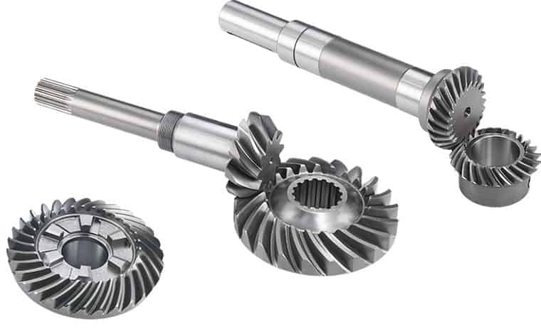
How does a bevel gear impact the overall efficiency of a system?
A bevel gear plays a significant role in determining the overall efficiency of a system. Its design, quality, and operating conditions can impact the efficiency of power transmission and the system as a whole. Here’s a detailed explanation of how a bevel gear can impact overall efficiency:
- Power Transmission Efficiency: The primary function of a bevel gear is to transmit power between intersecting shafts at different angles. The efficiency of power transmission through a bevel gear depends on factors such as gear geometry, tooth profile, material quality, lubrication, and operating conditions. In an ideally designed and well-maintained system, bevel gears can achieve high power transmission efficiency, typically above 95%. However, factors such as friction, misalignment, inadequate lubrication, and gear tooth wear can reduce efficiency and result in power losses.
- Friction and Mechanical Losses: Bevel gears experience friction between their mating teeth during operation. This friction generates heat and causes mechanical losses, reducing the overall efficiency of the system. Factors that affect friction and mechanical losses include the gear tooth profile, surface finish, lubrication quality, and operating conditions. High-quality gears with well-designed tooth profiles, proper lubrication, and optimized operating conditions can minimize friction and mechanical losses, improving the overall efficiency.
- Gear Tooth Design: The design of the bevel gear tooth profile influences its efficiency. Factors such as tooth shape, size, pressure angle, and tooth contact pattern affect the load distribution, friction, and efficiency. Proper tooth design, including optimized tooth profiles and contact patterns, help distribute the load evenly and minimize sliding between the teeth. Well-designed bevel gears with accurate tooth profiles can achieve higher efficiency by reducing friction and wear.
- Material Quality and Manufacturing Precision: The material quality and manufacturing precision of bevel gears impact their durability, smooth operation, and efficiency. High-quality materials with suitable hardness, strength, and wear resistance can minimize friction, wear, and power losses. Additionally, precise manufacturing processes ensure accurate gear geometry, tooth engagement, and alignment, optimizing the efficiency of power transmission and reducing losses due to misalignment or backlash.
- Lubrication and Wear: Proper lubrication is crucial for reducing friction, wear, and power losses in bevel gears. Insufficient or degraded lubrication can lead to metal-to-metal contact, increased friction, and accelerated wear, resulting in reduced efficiency. Adequate lubrication with the recommended lubricant type, viscosity, and replenishment schedule ensures a sufficient lubricating film between the gear teeth, minimizing friction and wear and improving overall efficiency.
- Misalignment and Backlash: Misalignment and excessive backlash in bevel gears can negatively impact efficiency. Misalignment causes uneven loading, increased friction, and accelerated wear. Excessive backlash results in power losses during direction changes and can lead to impact loads and vibration. Proper alignment and control of backlash within acceptable limits are crucial for maintaining high efficiency in a bevel gear system.
Overall, a well-designed bevel gear system with high-quality materials, accurate manufacturing, proper lubrication, and minimal losses due to friction, misalignment, or wear can achieve high efficiency in power transmission. Regular maintenance, monitoring, and optimization of operating conditions are essential to preserve the efficiency of the system over time.

What are the potential challenges in designing and manufacturing bevel gears?
Designing and manufacturing bevel gears can present several challenges due to their complex geometry, load requirements, and manufacturing processes. Here’s a detailed explanation of the potential challenges:
When it comes to designing and manufacturing bevel gears, the following challenges may arise:
- Complex Geometry: Bevel gears have intricate geometry with non-parallel and intersecting tooth profiles. Designing bevel gears requires a thorough understanding of gear theory, tooth engagement, and load distribution. The complex geometry poses challenges in determining the optimal tooth profile, tooth contact pattern, and gear ratios for the specific application.
- Load Analysis and Distribution: Determining the correct load analysis and distribution is crucial to ensure the gears can handle the anticipated forces and torques. Bevel gears often encounter varying loads, including radial loads, axial loads, and bending moments. Accurately predicting and distributing these loads across the gear teeth is essential for achieving proper gear strength, minimizing wear, and preventing premature failure.
- Manufacturing Precision: Bevel gears require high manufacturing precision to ensure smooth operation, minimal backlash, and efficient power transmission. Achieving the required precision in gear manufacturing involves precise machining, grinding, and heat treatment processes. The complex geometry of bevel gears adds to the manufacturing complexity, necessitating specialized equipment and skilled operators.
- Alignment Challenges: Proper alignment of bevel gears is critical for optimal performance and longevity. Achieving accurate alignment can be challenging due to the non-parallel shafts and intricate tooth profiles. Misalignment can lead to increased noise, vibration, and premature wear. Design considerations for alignment, as well as careful assembly and alignment procedures during manufacturing, are necessary to address this challenge.
- Lubrication and Cooling: Bevel gears require effective lubrication to minimize friction, wear, and heat generation. Ensuring proper lubrication and cooling can be challenging due to the unique shape of bevel gears and the limited space available for lubricant circulation. Designing appropriate lubrication systems, selecting suitable lubricants, and considering heat dissipation methods are essential for maintaining optimal gear performance and preventing overheating.
- Quality Control: Maintaining consistent quality during the manufacturing process is crucial for reliable bevel gears. Implementing robust quality control measures, including dimensional inspections, surface quality assessments, and gear testing, helps ensure that the manufactured gears meet the specified requirements. Consistency in gear quality is essential to minimize variations in performance and to ensure accurate gear meshing and load distribution.
Addressing these challenges requires a combination of engineering expertise, advanced manufacturing techniques, and quality control processes. Collaborating with experienced gear designers, employing state-of-the-art manufacturing technologies, and conducting thorough testing and analysis can help overcome these challenges and produce high-quality bevel gears that meet the performance and durability requirements of the intended application.

What is the purpose of using bevel gears in right-angle drives?
Using bevel gears in right-angle drives serves several purposes and offers advantages in transmitting power efficiently and smoothly at a 90-degree angle. Here’s a detailed explanation of the purpose of using bevel gears in right-angle drives:
- Change in Direction: One of the primary purposes of using bevel gears in right-angle drives is to change the direction of rotational motion. Bevel gears are designed to transmit power between intersecting or non-parallel shafts, allowing the input shaft and output shaft to be oriented at a 90-degree angle. This is particularly useful in applications where the space or mechanical constraints require a change in direction, such as in automotive differentials or power transmission systems that require a compact design.
- Space Efficiency: Bevel gears offer a space-efficient solution for right-angle drives. Their compact design allows for effective power transmission in applications with limited space. By using bevel gears, the drive system can be designed to occupy a smaller footprint compared to other mechanisms, making them suitable for applications where space is a critical consideration.
- Torque Transmission: Bevel gears are capable of transmitting high torque loads, making them suitable for right-angle drives. The meshing of the gear teeth provides a strong and reliable connection, allowing for efficient power transmission even at a 90-degree angle. This makes bevel gears suitable for applications that require the transmission of substantial torque, such as in industrial machinery, agricultural equipment, and heavy-duty power transmission systems.
- Speed Adjustment: Bevel gears in right-angle drives enable speed adjustment between the input and output shafts. By selecting bevel gears with different tooth counts, the rotational speed can be adjusted according to the desired output requirements. This feature is beneficial in applications where different speeds are needed for specific operations or to match the requirements of the driven equipment.
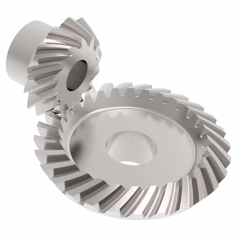
- Versatility: Bevel gears offer versatility in right-angle drives. They can be designed with different tooth profiles, such as straight-cut, spiral, or zerol, to optimize performance based on factors like noise reduction, load capacity, and efficiency. Additionally, bevel gears can be manufactured from different materials, allowing them to withstand different environmental conditions and requirements.
- Smooth Operation: Bevel gears, especially spiral bevel gears, provide smooth and efficient operation in right-angle drives. The gradual engagement of the curved teeth reduces noise, vibration, and shock during gear meshing, resulting in quieter operation and improved overall system performance.
- Wide Range of Applications: Bevel gears find extensive applications in right-angle drives across various industries. They are commonly used in automotive differentials, marine propulsion systems, industrial machinery, robotics, aerospace systems, and more. The ability to transmit power at a 90-degree angle efficiently and reliably makes bevel gears suitable for a wide range of applications.
In summary, using bevel gears in right-angle drives offers benefits such as changing the direction of motion, space efficiency, torque transmission, speed adjustment, versatility, smooth operation, and suitability for a wide range of applications. These advantages make bevel gears a preferred choice in numerous industries and systems that require efficient and reliable power transmission at a 90-degree angle.


editor by Dream 2024-04-23

Recent Comments