Product Description
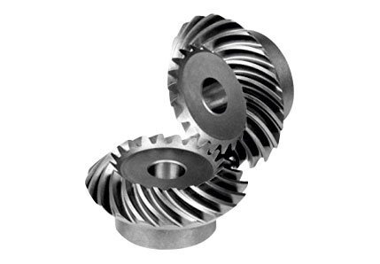
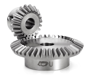
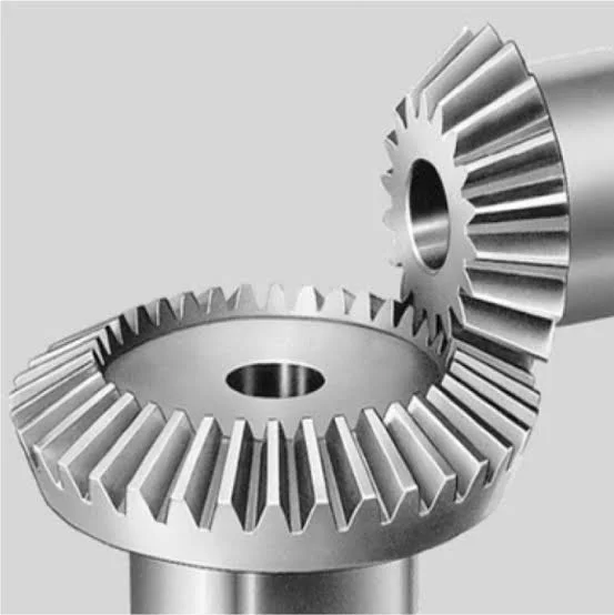
OEM High-Intensity Precision Machined Steel Bevel Gears
At CHINAMFG Industry, we use the latest machining technology with a wide range of capabilities to meet your demands. Our manufacturing facilities include 3-5 axis milling, lathes, grinding, etc, and state of the art metrology. With these machines, we produce complex parts in the most efficient and accurate way. Our manufacturing capabilities allow us to develop your part from prototype to mass production for the most precise of jobs.
| Processing Method | CNC Milling, CNC Turning, Turning-Milling Machining, Micro Machining, Grinding, Boring, Tapping. |
| Material | Stainless Steel, Alloy Steel, Carbon Steel, Free-cutting Steel, Brass, Copper, Aluminum, POM, PTFE. |
| Finish Treatment | Polishing, Sand Blasting, Anodizing, Zinc Plating, Nickel Plating, Blackening, QPQ, Painting, etc.. |
| Tech. Standard | ANSI, ASTM, DIN, JIS, BS, GB, ISO, etc.. |
| Application | Medical, Aerospace, Millitary, Instrument, Optics, Food Equipment, AUTO Parts, Furniture, etc.. |
Precision Machining is the most important sector in CHINAMFG Industry, we have been a trusted manufacturing supplier in this field for over 15 years. We have built an impeccable reputation on quality, customer service and utilizing state-of-the-art equipment. Our expertise has made us the Best in Quality and Innovation.
Machining Facilities
| Equipment Description | Workpiece Dimensions | Processing Accuracy | Quantities | Brand |
| 3-axis machining center | Max. 1000 x 1200mm | +/-0.01mm | 6 | DMG |
| 4-axis machining center | Max. 1000 x 1500mm | +/-0.01mm | 4 | DMG |
| 5-axis machining center | Max. 1000 x 1500mm | +/-0.01mm | 2 | DMG |
| CNC lathe | Max. diameter 100mm | +/-0.01mm | 20 | SMTCL |
| General lathe | Max. diameter 500mm | +/-0.05mm | 2 | SMTCL |
| Turning-Milling machine | Max. diameter 100mm | +/-0.01mm | 6 | DMG |
| Longitudinal lathe | Max. diameter 30mm | +/-0.01mm | 6 | TSUGAMI |
| Automatic lathe | Max. diameter 20mm | +/-0.02mm | 30 | TY |
| CNC Swiss Lathe | Max. diameter 20mm | +/-0.01mm | 6 | TSUGAMI |
Other assist equipments include:
Milling machine, Drilling machine, Centerless Grinding machine, External Cylindrical Grinding machine, etc.
Inspection equipment:
Vernier Caliper, Micrometer, Height Gage, Hardness Tester, Two-dimensional image measuring instrument, TESA Micro-Hite 300, Mitutoyo surface Roughness Tester, Mitutoyo CMM and Ultrasonic Cleaner.
FAQ
Q1: Are you a trading company or a manufacturer?
Manufacturer.
Q2: How long is your delivery time?
Normally, the samples delivery is 10-15 days and the lead time for the official order is 30-45 days.
Q3: How long will it take to quote the RFQs?
Normally, it will take 2-3 days.
Q4: Do you provide samples?
Yes, the samples will be free if the cost is not too high.
Q5: Which countries are your target markets?
America, Canada, Europe, Australia and New Zealand.
Q6: Do you have experience of doing business with overseas customers?
Yes, we have over 10 years exporting experience and 95% of our products were exported to overseas market. We specialized in the high quality OEM parts, we are familiar with the standard of ANSI, DIN, ISO, BS, JIS, etc..
Q7: Do you have reference customers?
Yes, we have been appointed as the supplier of Parker(USA) since 2012. “Supply the top quality precision machined parts” is our management philosophy, ON TIME
and EVERYTIME.
/* January 22, 2571 19:08:37 */!function(){function s(e,r){var a,o={};try{e&&e.split(“,”).forEach(function(e,t){e&&(a=e.match(/(.*?):(.*)$/))&&1
| Application: | Motor, Electric Cars, Motorcycle, Machinery, Marine, Toy, Agricultural Machinery, Car |
|---|---|
| Hardness: | Hardened Tooth Surface |
| Gear Position: | External Gear |
| Manufacturing Method: | Cut Gear |
| Toothed Portion Shape: | Bevel Wheel |
| Material: | Stainless Steel |
| Samples: |
US$ 10/Piece
1 Piece(Min.Order) | |
|---|
| Customization: |
Available
| Customized Request |
|---|

How do you prevent backlash and gear play in a bevel gear mechanism?
In a bevel gear mechanism, preventing backlash and gear play is essential for ensuring accurate and efficient power transmission. Backlash refers to the clearance or free movement between the mating teeth of gears, resulting in a brief loss of motion or a dead zone when changing direction. Here are some methods to prevent backlash and minimize gear play in a bevel gear mechanism:
- Precision Manufacturing: High-precision manufacturing processes are crucial for minimizing backlash and gear play in bevel gears. Accurate machining of gear teeth and precise control of tooth dimensions, profiles, and alignment help achieve tight meshing between the gears, reducing the clearance and backlash. Modern manufacturing techniques, such as CNC machining and gear grinding, can ensure the desired level of precision and minimize gear play.
- Proper Gear Design: The design of the bevel gears can influence the amount of backlash and gear play. An optimized gear design, including suitable tooth profiles, pressure angles, and tooth contact patterns, can help distribute the load evenly and minimize the clearance between the mating teeth. By carefully considering gear design parameters, designers can reduce backlash and improve gear meshing characteristics.
- Preload or Pre-Tension: Applying a preload or pre-tension to the bevel gears can help minimize backlash and gear play. This involves applying a slight force or tension to the gears, forcing them to maintain contact and reducing the clearance between the teeth. Preload can be achieved through various methods, such as using spring mechanisms, shimming, or adjusting the mounting position of the gears.
- Backlash Compensation: Backlash compensation methods aim to minimize the effects of backlash and gear play by introducing mechanisms or techniques that compensate for the clearance. One common approach is to use anti-backlash gears, which have special tooth profiles or arrangements that reduce or eliminate clearance between the mating teeth. Another method is to incorporate backlash compensation devices, such as spring-loaded mechanisms or adjustable shims, that actively reduce the backlash during operation.
- Tight Control of Tolerances: Maintaining tight tolerances during the manufacturing and assembly processes is critical for minimizing backlash and gear play. Close control of dimensions, alignment, and clearances ensures proper gear meshing and reduces the possibility of excessive play. Quality control measures, such as inspection, testing, and verification of gear dimensions, can help ensure that the gears meet the specified tolerances.
- Regular Maintenance: Regular maintenance practices, including inspection, lubrication, and adjustment, are essential for preventing and minimizing backlash and gear play over time. Periodic checks for wear, misalignment, and proper lubrication can help identify and rectify any issues that may contribute to increased backlash. Timely maintenance and replacement of worn or damaged gears can help maintain optimal gear meshing and minimize play.
By implementing these methods, it is possible to significantly reduce backlash and gear play in a bevel gear mechanism, resulting in improved accuracy, efficiency, and longevity of the gear system.

Can bevel gears be used in heavy-duty machinery and equipment?
Yes, bevel gears can be used in heavy-duty machinery and equipment due to their ability to transmit high torque, handle heavy loads, and operate in various orientations. Here’s a detailed explanation:
Bevel gears are versatile and robust, making them suitable for heavy-duty applications in machinery and equipment. Here are several reasons why bevel gears are commonly used in heavy-duty applications:
- High Torque Transmission: Bevel gears are capable of transmitting high torque between intersecting shafts. They have a large contact area, which allows for efficient power transmission without compromising strength. This makes them well-suited for heavy-duty machinery that requires high torque output.
- Heavy Load Handling: Bevel gears are designed to withstand heavy loads, including radial loads, axial loads, and bending moments. Their sturdy construction and tooth geometry enable them to distribute the load evenly across the gear teeth, minimizing localized stress and preventing premature failure. This load-handling capability makes bevel gears ideal for heavy-duty applications that involve substantial forces and loads.
- Various Orientations: Bevel gears can be used in different orientations, including horizontal, vertical, and angled arrangements. This versatility allows them to adapt to the specific requirements of heavy-duty machinery and equipment, regardless of the shaft orientation. Whether it’s a gearbox, power transmission system, or lifting equipment, bevel gears can be designed and installed to accommodate the desired orientation.
- Durable Construction: Bevel gears are typically manufactured using high-strength materials, such as alloy steels or case-hardened steels, to ensure durability and resistance to wear. They undergo precise machining, grinding, and heat treatment processes to achieve the required hardness, surface finish, and dimensional accuracy. The robust construction and quality manufacturing of bevel gears make them capable of withstanding the demanding conditions of heavy-duty applications.
- Application-Specific Designs: Bevel gears can be customized and optimized for specific heavy-duty applications. Gear designers can tailor the gear parameters, such as tooth profile, size, and material selection, to match the requirements of the machinery or equipment. This flexibility in design allows for the creation of bevel gears that are specifically engineered to handle the unique demands of heavy-duty applications.
Overall, bevel gears are well-suited for heavy-duty machinery and equipment due to their high torque transmission capability, load-handling capacity, adaptability to various orientations, durable construction, and customizable designs. By selecting the appropriate bevel gear types, sizes, and materials, engineers can ensure reliable and efficient operation in heavy-duty applications across industries such as construction, mining, agriculture, and transportation.
It is important to note that the specific design requirements and load conditions of each heavy-duty application should be carefully considered during the gear selection and design process. Consulting with experienced engineers and adhering to industry standards will help ensure that the chosen bevel gears are suitable for the intended heavy-duty machinery or equipment.

How do you calculate the gear ratio of a bevel gear?
Calculating the gear ratio of a bevel gear involves determining the ratio between the number of teeth on the driving gear (pinion) and the driven gear (crown gear). Here’s a detailed explanation of how to calculate the gear ratio of a bevel gear:
The gear ratio is determined by the relationship between the number of teeth on the pinion and the crown gear. The gear ratio is defined as the ratio of the number of teeth on the driven gear (crown gear) to the number of teeth on the driving gear (pinion). It can be calculated using the following formula:
Gear Ratio = Number of Teeth on Crown Gear / Number of Teeth on Pinion Gear
For example, let’s consider a bevel gear system with a crown gear that has 40 teeth and a pinion gear with 10 teeth. The gear ratio can be calculated as follows:
Gear Ratio = 40 / 10 = 4
In this example, the gear ratio is 4:1, which means that for every four revolutions of the driving gear (pinion), the driven gear (crown gear) completes one revolution.
It’s important to note that the gear ratio can also be expressed as a decimal or a percentage. For the example above, the gear ratio can be expressed as 4 or 400%.
Calculating the gear ratio is essential for understanding the speed relationship and torque transmission between the driving and driven gears in a bevel gear system. The gear ratio determines the relative rotational speed and torque amplification or reduction between the gears.
It’s worth mentioning that the gear ratio calculation assumes ideal geometries and does not consider factors such as backlash, efficiency losses, or any other system-specific considerations. In practical applications, it’s advisable to consider these factors and consult gear manufacturers or engineers for more accurate calculations and gear selection.
In summary, the gear ratio of a bevel gear is determined by dividing the number of teeth on the crown gear by the number of teeth on the pinion gear. The gear ratio defines the speed and torque relationship between the driving and driven gears in a bevel gear system.


editor by CX 2024-04-17

Recent Comments