Product Description
Spur Gear Plastic Stainless Steel aluminum Motor Wheel Diameter Bevel Gear DC Shafts Pin Nylon Bore Tooth Brass Steels Shaft Miniature Auto cylindrical Gear
Spur gears are a type of cylindrical gear, with shafts that are parallel and coplanar, and teeth that are straight and oriented parallel to the shafts. They’re arguably the simplest and most common type of gear – easy to manufacture and suitable for an array of applications.
1.Material: Alloy Steel, Carbon Steel, Stainless Steel, Harden & Tempered Steel, Cast Iron, Aluminum, Copper, Brass nylon and so on.
2. Heat Treatment: Hardening and Tempering, High Frequency Quenching, Carburizing Quenching and so on.
3. Pilot bore, finished bore, taper bore and special bore.
4. Bright surface and high precision
5. Advanced heat treatment and surface treatment craft
6. Better quality and competitive price.
7. Convenient to transport and handle
8. High strength
9. Corrosion resistance
10. Easy to install
11. Long life span
12. OEM/ODM welcome
There are 2 primary types of spur gears: external and internal. Exterior gears have the teeth that are cut externally surface area of the cylinder. Two external gears mesh with each other and rotate in opposite directions. Internal gears, in contrast, have teeth that are cut on the inside surface of the cylinder. An external gear sits inside the internal gear, and the gears rotate in the same direction. Because the shafts are positioned closer together, internal gear assemblies are more compact than external gear assemblies. Internal gears are primarily used for planetary gear drives.
/* January 22, 2571 19:08:37 */!function(){function s(e,r){var a,o={};try{e&&e.split(“,”).forEach(function(e,t){e&&(a=e.match(/(.*?):(.*)$/))&&1
| Application: | Motor, Machinery |
|---|---|
| Hardness: | Hardened Tooth Surface |
| Gear Position: | Internal Gear |
| Manufacturing Method: | Rolling Gear |
| Toothed Portion Shape: | Spur Gear |
| Material: | Cast Steel |
| Samples: |
US$ 999/Piece
1 Piece(Min.Order) | |
|---|

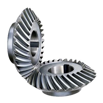
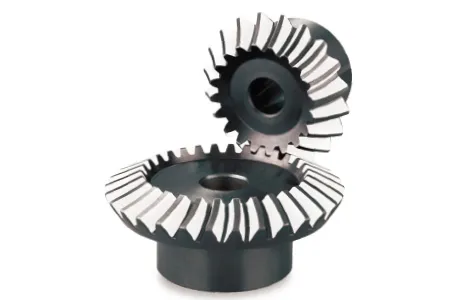
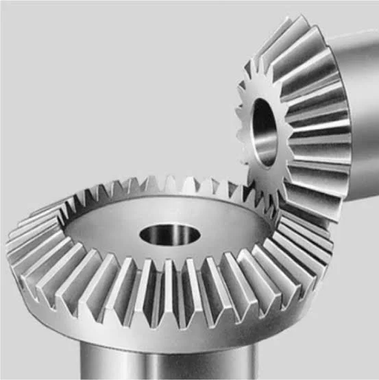
Can bevel gears be used in precision manufacturing equipment?
Yes, bevel gears can be used in precision manufacturing equipment due to their ability to transmit motion and power at varied angles with high accuracy. Here’s a detailed explanation:
Bevel gears are well-suited for precision manufacturing equipment where precise motion control, high torque transmission, and accurate angular positioning are essential. Here are some key reasons why bevel gears are suitable for such applications:
- Angular Transmission: Bevel gears excel at transmitting motion and power between intersecting shafts at different angles. In precision manufacturing equipment, where components often require precise angular positioning, bevel gears provide an efficient means of achieving the necessary motion transfer. They allow for smooth and accurate rotation, ensuring precise alignment and positioning of machine components.
- Compact Design: Bevel gears have a compact design, making them suitable for applications where space is limited. In precision manufacturing equipment, where machines often have complex structures and require tight integration of components, the compact size of bevel gears allows for efficient utilization of available space. This is particularly advantageous when designing compact and high-precision machinery.
- High Torque Transmission: Bevel gears are capable of transmitting high torque loads, making them suitable for precision manufacturing equipment that requires the transmission of substantial power. Whether it’s in rotary tables, indexing mechanisms, or gearboxes, bevel gears can efficiently transfer high torque while maintaining accuracy and precision in motion control.
- Accuracy and Backlash Control: In precision manufacturing equipment, minimizing backlash and ensuring accurate motion control are critical. Bevel gears can be manufactured with high precision to achieve tight tolerances and minimal backlash. This allows for precise positioning, accurate motion control, and repeatable performance, which are essential in precision manufacturing processes.
- Customization Options: Bevel gears can be customized to meet specific requirements of precision manufacturing equipment. Different tooth profiles, gear ratios, materials, and surface treatments can be employed to optimize the gear performance for specific applications. This customization capability allows gear engineers to design bevel gears that precisely match the needs and specifications of the equipment.
Examples of precision manufacturing equipment where bevel gears are commonly used include CNC machines, milling machines, gear hobbing machines, rotary tables, indexing mechanisms, and various types of gearboxes. These machines rely on the precise and reliable motion transmission provided by bevel gears to achieve accurate and high-quality manufacturing processes.
It is important to note that the selection and design of bevel gears for precision manufacturing equipment should consider factors such as load requirements, speed, operating conditions, backlash limitations, and noise considerations. Gear engineers and machine designers often conduct detailed analyses and calculations to ensure the bevel gears meet the necessary performance criteria and contribute to the overall precision and reliability of the equipment.
In summary, bevel gears are well-suited for precision manufacturing equipment due to their ability to provide accurate angular transmission, compact design, high torque transmission, and customization options. Incorporating bevel gears in precision machinery contributes to precise motion control, accurate positioning, and reliable performance, enabling the production of high-quality and precise manufactured components.

How do you ensure proper alignment when connecting a bevel gear?
Proper alignment is crucial when connecting a bevel gear to ensure efficient power transmission, smooth operation, and longevity of the gear system. Here’s a detailed explanation of how to ensure proper alignment:
When connecting a bevel gear, the following steps can help ensure proper alignment:
- Check Gear Specifications: Begin by reviewing the gear specifications provided by the manufacturer. This includes information about the gear’s design, tolerances, and alignment requirements. Understanding these specifications is essential for achieving the desired alignment.
- Prepare Mounting Surfaces: Ensure that the mounting surfaces for the gears, such as shafts or gearboxes, are clean, free from debris, and properly prepared. Any irregularities or surface defects can affect the alignment and lead to misalignment issues. Remove any burrs, nicks, or rough spots that could interfere with the proper seating of the gears.
- Use Alignment Tools: Alignment tools, such as dial indicators or laser alignment systems, can be helpful in achieving precise alignment. These tools allow for accurate measurement and adjustment of the gear’s position relative to the mating components. Follow the instructions provided with the alignment tools to set up and perform the alignment process correctly.
- Axial Alignment: Achieving proper axial alignment is crucial for bevel gears. The axial alignment refers to aligning the gear’s rotational axis parallel to the mating gear’s rotational axis. This ensures proper gear meshing and load distribution. Use alignment tools to measure and adjust the axial alignment, making necessary modifications to the gear’s position or shimming as required.
- Radial Alignment: Radial alignment involves aligning the gear’s rotational axis perpendicular to the mating gear’s rotational axis. Proper radial alignment helps prevent side loads, excessive wear, and noise generation. Use alignment tools to measure and adjust the radial alignment, ensuring that the gear’s position is properly adjusted or shimmed to achieve the desired alignment.
- Verify Tooth Contact Pattern: After aligning the gears, it is important to verify the tooth contact pattern. The tooth contact pattern should be evenly distributed across the gear tooth surfaces to ensure proper load sharing and minimize wear. Conduct a visual inspection or use specialized tools, such as gear marking compounds, to check and adjust the tooth contact pattern if necessary.
By following these steps and using appropriate alignment tools, you can ensure proper alignment when connecting a bevel gear. Proper alignment promotes efficient power transmission, minimizes wear, reduces noise, and extends the lifespan of the gear system.
It is worth noting that each gear system may have specific alignment requirements and considerations. Consult the gear manufacturer’s guidelines and best practices, as well as seek the expertise of experienced engineers, to ensure the proper alignment of bevel gears in your specific application.

How do you calculate the gear ratio of a bevel gear?
Calculating the gear ratio of a bevel gear involves determining the ratio between the number of teeth on the driving gear (pinion) and the driven gear (crown gear). Here’s a detailed explanation of how to calculate the gear ratio of a bevel gear:
The gear ratio is determined by the relationship between the number of teeth on the pinion and the crown gear. The gear ratio is defined as the ratio of the number of teeth on the driven gear (crown gear) to the number of teeth on the driving gear (pinion). It can be calculated using the following formula:
Gear Ratio = Number of Teeth on Crown Gear / Number of Teeth on Pinion Gear
For example, let’s consider a bevel gear system with a crown gear that has 40 teeth and a pinion gear with 10 teeth. The gear ratio can be calculated as follows:
Gear Ratio = 40 / 10 = 4
In this example, the gear ratio is 4:1, which means that for every four revolutions of the driving gear (pinion), the driven gear (crown gear) completes one revolution.
It’s important to note that the gear ratio can also be expressed as a decimal or a percentage. For the example above, the gear ratio can be expressed as 4 or 400%.
Calculating the gear ratio is essential for understanding the speed relationship and torque transmission between the driving and driven gears in a bevel gear system. The gear ratio determines the relative rotational speed and torque amplification or reduction between the gears.
It’s worth mentioning that the gear ratio calculation assumes ideal geometries and does not consider factors such as backlash, efficiency losses, or any other system-specific considerations. In practical applications, it’s advisable to consider these factors and consult gear manufacturers or engineers for more accurate calculations and gear selection.
In summary, the gear ratio of a bevel gear is determined by dividing the number of teeth on the crown gear by the number of teeth on the pinion gear. The gear ratio defines the speed and torque relationship between the driving and driven gears in a bevel gear system.


editor by Dream 2024-04-30

Recent Comments