Product Description
XIHU (WEST LAKE) DIS.HUA Chain Group is the most professional manufacturer of power transmission in China, manufacturing roller chains, industry sprockets, motorcycle sprockets, casting sprockets, different type of couplings, pulleys, taper bushes, locking devices, gears, shafts, CNC precision parts and so on. We have passed ISO9001, ISO14001, TS16949 such quality and enviroment certification.
PRODUCT DESCRIPITION:
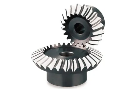
Standard bevel gear with spline
Gear with straight teeth
Mould from 0.5–16
MaterialLcast iron, 20CrMnTi, 20Cr, 40Cr
Carburization
High quality lubrication.
20 degree pressure angle
Type: B(with 1 hub)
| Product name | DIN Standard Bevel Gear with Spline Mod1.5,15T |
| Materials Available | 1. Stainless Steel: SS201, SS303, SS304, SS316, SS416, SS420 |
| 2. Steel:C45(K1045), C46(K1046),C20 | |
| 3. Brass:C36000 ( C26800), C37700 ( HPb59), C38500( HPb58), C27200(CuZn37), C28000(CuZn40) | |
| 4. Bronze: C51000, C52100, C54400, etc | |
| 5. Iron: 1213, 12L14,1215 | |
| 6. Aluminum: Al6061, Al6063 | |
| 7.OEM according to your request | |
| Surface Treatment | Annealing, natural anodization, heat treatment, polishing, nickel plating, chrome plating, znic plating,yellow passivation, gold passivation, satin, Black surface painted etc. |
| Products Available | sprockt chains, pulley, shafts(axles, spline shafts, dart shafts),gears (pinions, wheels gear rack) bearing, bearing seat, bushing, coupling, lock assembly etc. |
| Processing Method | CNC machining, punch,turning, milling, drilling, grinding, broaching, welding and assembly |
| QC : | Technicians self-check in production,final-check before package by professional Quality inspector |
| Size | Drawings |
| Package | Wooden Case/Container and pallet, or as per customized specifications |
| Certificate | ISO9001:2008 , ISO14001:2001,ISO/TS 16949:2009 |
| Advantage | Quality first Service superior , Advanced equipment,Experienced workers,Perfect testing equipment |
| Lead Time | 15-25days samples. 30-45days offcial order |
/* January 22, 2571 19:08:37 */!function(){function s(e,r){var a,o={};try{e&&e.split(“,”).forEach(function(e,t){e&&(a=e.match(/(.*?):(.*)$/))&&1
| Application: | Agricultural |
|---|---|
| Hardness: | Hardened |
| Manufacturing Method: | Cast Gear |
| Toothed Portion Shape: | Bevel Wheel |
| Material: | C45, Cast Iron |
| Type: | Bevel Gear |
| Customization: |
Available
| Customized Request |
|---|

Are bevel gears suitable for high-torque applications?
Bevel gears can indeed be suitable for high-torque applications, depending on various factors such as the specific design, material selection, and proper application engineering. Here’s a detailed explanation:
Bevel gears are known for their ability to transmit power between intersecting shafts at different angles. They can handle significant torque loads and are commonly used in applications that require high-torque transmission. However, the suitability of bevel gears for high-torque applications depends on the following factors:
- Design: The design of the bevel gears plays a crucial role in their ability to handle high torque. Factors such as tooth profile, size, and geometry impact the load-carrying capacity and torque transmission capability. Bevel gears with robust and optimized designs, including suitable tooth profiles and adequate tooth engagement, can effectively handle high-torque applications.
- Material Selection: The choice of materials for bevel gears is critical in high-torque applications. Gears need to be made from materials with high strength, hardness, and wear resistance to withstand the forces and stresses involved in transmitting high torque. Common materials used for bevel gears include alloy steels, carburizing steels, and specialty alloys. Material selection should consider the specific torque requirements, operating conditions, and anticipated loads to ensure the gears can handle the desired torque levels.
- Lubrication: Proper lubrication is essential for reducing friction, wear, and heat generation in high-torque bevel gear applications. Adequate lubrication helps maintain a lubricating film between the gear teeth, minimizing metal-to-metal contact and associated losses. The lubricant type, viscosity, and replenishment schedule should be selected based on the torque and operating conditions to ensure effective lubrication and minimize gear wear.
- Gear Size and Ratio: The size of the bevel gears and the gear ratio can influence their torque-handling capability. Larger gears generally have greater tooth strength and load-carrying capacity, making them more suitable for high-torque applications. The gear ratio should also be considered to ensure it is appropriate for the desired torque transmission and to avoid excessive loads on the gears.
- Operating Conditions: The operating conditions, including speed, temperature, and shock loads, must be taken into account when determining the suitability of bevel gears for high-torque applications. Higher speeds and extreme operating temperatures can affect the gear material properties, lubrication performance, and overall gear system efficiency. Proper cooling, temperature control, and gear protection measures should be implemented to maintain reliable performance under high-torque conditions.
By considering these factors and properly engineering the bevel gear system, it is possible to utilize bevel gears in high-torque applications effectively. However, it is crucial to consult with experienced engineers and perform thorough analysis and testing to ensure the gears can handle the specific torque requirements of the application.

How do you ensure proper alignment when connecting a bevel gear?
Proper alignment is crucial when connecting a bevel gear to ensure efficient power transmission, smooth operation, and longevity of the gear system. Here’s a detailed explanation of how to ensure proper alignment:
When connecting a bevel gear, the following steps can help ensure proper alignment:
- Check Gear Specifications: Begin by reviewing the gear specifications provided by the manufacturer. This includes information about the gear’s design, tolerances, and alignment requirements. Understanding these specifications is essential for achieving the desired alignment.
- Prepare Mounting Surfaces: Ensure that the mounting surfaces for the gears, such as shafts or gearboxes, are clean, free from debris, and properly prepared. Any irregularities or surface defects can affect the alignment and lead to misalignment issues. Remove any burrs, nicks, or rough spots that could interfere with the proper seating of the gears.
- Use Alignment Tools: Alignment tools, such as dial indicators or laser alignment systems, can be helpful in achieving precise alignment. These tools allow for accurate measurement and adjustment of the gear’s position relative to the mating components. Follow the instructions provided with the alignment tools to set up and perform the alignment process correctly.
- Axial Alignment: Achieving proper axial alignment is crucial for bevel gears. The axial alignment refers to aligning the gear’s rotational axis parallel to the mating gear’s rotational axis. This ensures proper gear meshing and load distribution. Use alignment tools to measure and adjust the axial alignment, making necessary modifications to the gear’s position or shimming as required.
- Radial Alignment: Radial alignment involves aligning the gear’s rotational axis perpendicular to the mating gear’s rotational axis. Proper radial alignment helps prevent side loads, excessive wear, and noise generation. Use alignment tools to measure and adjust the radial alignment, ensuring that the gear’s position is properly adjusted or shimmed to achieve the desired alignment.
- Verify Tooth Contact Pattern: After aligning the gears, it is important to verify the tooth contact pattern. The tooth contact pattern should be evenly distributed across the gear tooth surfaces to ensure proper load sharing and minimize wear. Conduct a visual inspection or use specialized tools, such as gear marking compounds, to check and adjust the tooth contact pattern if necessary.
By following these steps and using appropriate alignment tools, you can ensure proper alignment when connecting a bevel gear. Proper alignment promotes efficient power transmission, minimizes wear, reduces noise, and extends the lifespan of the gear system.
It is worth noting that each gear system may have specific alignment requirements and considerations. Consult the gear manufacturer’s guidelines and best practices, as well as seek the expertise of experienced engineers, to ensure the proper alignment of bevel gears in your specific application.

Can you explain the concept of straight and spiral bevel gears?
Straight and spiral bevel gears are two common types of bevel gears that have different tooth geometries and characteristics. Here’s a detailed explanation of the concept of straight and spiral bevel gears:
Straight Bevel Gears:
Straight bevel gears are a type of bevel gears with straight-cut teeth that are machined on the cone-shaped surface of the gears. The teeth of straight bevel gears are parallel to the gear axis and intersect at a 90-degree angle. These gears are often used when the intersecting shafts need to transmit rotational motion at a right angle.
Straight bevel gears have the following characteristics:
- Tooth Engagement: In straight bevel gears, the tooth engagement occurs gradually as the gears rotate. This results in a relatively smooth and continuous transfer of power between the gears.
- Noise and Vibration: Straight bevel gears can produce more noise and vibration compared to other types of bevel gears, particularly at higher speeds. The straight-cut teeth create impact and noise during the engagement process.
- Efficiency: Straight bevel gears have relatively high efficiency due to their simple tooth geometry and direct engagement.
- Applications: Straight bevel gears are commonly used in applications such as automotive differentials, hand drills, and other mechanical power transmission systems where a 90-degree change in direction is required.
Spiral Bevel Gears:
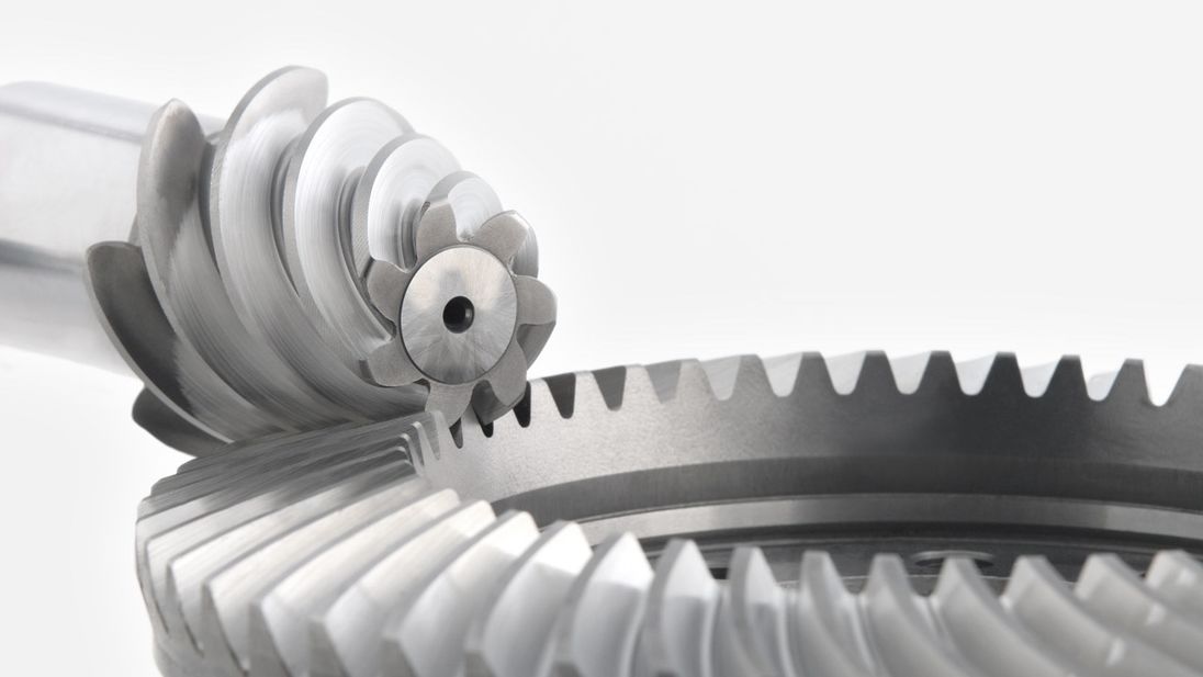
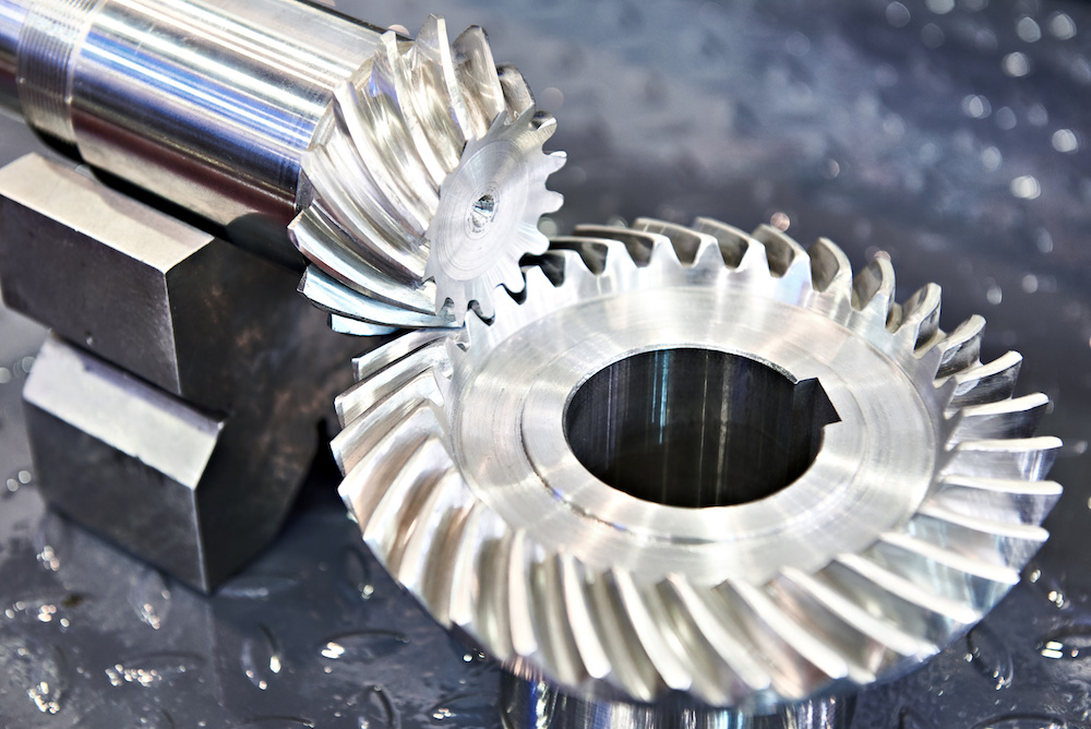
Spiral bevel gears are another type of bevel gears with curved teeth that are machined on the cone-shaped surface of the gears. The teeth of spiral bevel gears are cut in a spiral pattern, gradually curving along the gear surface. This spiral tooth geometry provides several advantages over straight bevel gears.
Spiral bevel gears have the following characteristics:
- Tooth Engagement: Spiral bevel gears have a more gradual and smoother tooth engagement compared to straight bevel gears. The spiral-shaped teeth allow for progressive contact between the gears, resulting in reduced impact, noise, and vibration.
- Noise and Vibration: Spiral bevel gears produce less noise and vibration compared to straight bevel gears due to their improved tooth engagement characteristics.
- Load Capacity: Spiral bevel gears have higher load-carrying capacity compared to straight bevel gears due to the increased contact area between the gear teeth. This makes them suitable for applications that require higher torque transmission.
- Efficiency: Spiral bevel gears have slightly lower efficiency compared to straight bevel gears due to the sliding action between the teeth during engagement. However, advancements in gear design and manufacturing techniques have improved their efficiency.
- Applications: Spiral bevel gears are commonly used in applications where smooth and quiet operation is required, such as automotive rear axle drives, machine tools, and industrial machinery.
In summary, straight bevel gears have straight-cut teeth that intersect at a 90-degree angle, while spiral bevel gears have curved teeth that engage in a spiral pattern. Straight bevel gears are suitable for applications that require a right angle change in direction, while spiral bevel gears provide smoother engagement, reduced noise, and higher load-carrying capacity. The selection between straight and spiral bevel gears depends on the specific requirements of the application, including the desired level of noise, vibration, efficiency, and torque transmission.


editor by Dream 2024-05-07

Recent Comments