Product Description
|
Material |
Non-ferrous alloy material like carbon steel, stainless steel, galvanized steel, aluminum, copper, brass, etc |
|
Surface Finish: |
All kinds of surface treatment are available like chrome plating, zinc plating , nick plating , powder coating, e-coating, dip coating, mirror polishing, etc. |
|
Application |
Electronic/Appliance/Auto/Industrial equipment metal stamping hardware parts |
|
Processing |
Our process includes tooling fabrication, stamping, deep drawing, punching, spinning, laser cutting, bending, seamless welding, machining and assembly |
|
AvailableCertificate |
ISO 9001, SGS, Material Certificate |
|
Accident Prevention |
Safety Operation Management |
|
Quality Control |
Liability System and Periodical QC on line every hour |
|
Main Market |
USA/Germany/Canada/Italy/United Kingdom/Australia/Pakistan/French , etc |
HangZhou CHINAMFG Industry Co., Ltd. is a specialized supplier of a full range of chains, sprockets, gears, gear racks, v belt pulley, timing pulley, V-belts, couplings, machined parts and so on.
Due to our CHINAMFG in offering best service to our clients, understanding of your needs and overriding sense of responsibility toward filling ordering requirements, we have obtained the trust of buyers worldwide. Having accumulated precious experience in cooperating with foreign customers, our products are selling well in the American, European, South American and Asian markets. Our products are manufactured by modern computerized machinery and equipment. Meanwhile, our products are manufactured according to high quality standards, and complying with the international advanced standard criteria.
With many years’ experience in this line, we will be trusted by our advantages in competitive price, one-time delivery, prompt response, on-hand engineering support and good after-sales services.
Additionally, all our production procedures are in compliance with ISO9001 standards. We also can design and make non-standard products to meet customers’ special requirements. Quality and credit are the bases that make a corporation alive. We will provide best services and high quality products with all sincerity. If you need any information or samples, please contact us and you will have our soon reply.
/* January 22, 2571 19:08:37 */!function(){function s(e,r){var a,o={};try{e&&e.split(“,”).forEach(function(e,t){e&&(a=e.match(/(.*?):(.*)$/))&&1
| Condition: | New |
|---|---|
| Axle Number: | 2 |
| Application: | Truck |
| Certification: | CE |
| Material: | Alloy |
| Type: | Rear Axles |
| Customization: |
Available
| Customized Request |
|---|

How does a bevel gear impact the overall efficiency of a system?
A bevel gear plays a significant role in determining the overall efficiency of a system. Its design, quality, and operating conditions can impact the efficiency of power transmission and the system as a whole. Here’s a detailed explanation of how a bevel gear can impact overall efficiency:
- Power Transmission Efficiency: The primary function of a bevel gear is to transmit power between intersecting shafts at different angles. The efficiency of power transmission through a bevel gear depends on factors such as gear geometry, tooth profile, material quality, lubrication, and operating conditions. In an ideally designed and well-maintained system, bevel gears can achieve high power transmission efficiency, typically above 95%. However, factors such as friction, misalignment, inadequate lubrication, and gear tooth wear can reduce efficiency and result in power losses.
- Friction and Mechanical Losses: Bevel gears experience friction between their mating teeth during operation. This friction generates heat and causes mechanical losses, reducing the overall efficiency of the system. Factors that affect friction and mechanical losses include the gear tooth profile, surface finish, lubrication quality, and operating conditions. High-quality gears with well-designed tooth profiles, proper lubrication, and optimized operating conditions can minimize friction and mechanical losses, improving the overall efficiency.
- Gear Tooth Design: The design of the bevel gear tooth profile influences its efficiency. Factors such as tooth shape, size, pressure angle, and tooth contact pattern affect the load distribution, friction, and efficiency. Proper tooth design, including optimized tooth profiles and contact patterns, help distribute the load evenly and minimize sliding between the teeth. Well-designed bevel gears with accurate tooth profiles can achieve higher efficiency by reducing friction and wear.
- Material Quality and Manufacturing Precision: The material quality and manufacturing precision of bevel gears impact their durability, smooth operation, and efficiency. High-quality materials with suitable hardness, strength, and wear resistance can minimize friction, wear, and power losses. Additionally, precise manufacturing processes ensure accurate gear geometry, tooth engagement, and alignment, optimizing the efficiency of power transmission and reducing losses due to misalignment or backlash.
- Lubrication and Wear: Proper lubrication is crucial for reducing friction, wear, and power losses in bevel gears. Insufficient or degraded lubrication can lead to metal-to-metal contact, increased friction, and accelerated wear, resulting in reduced efficiency. Adequate lubrication with the recommended lubricant type, viscosity, and replenishment schedule ensures a sufficient lubricating film between the gear teeth, minimizing friction and wear and improving overall efficiency.
- Misalignment and Backlash: Misalignment and excessive backlash in bevel gears can negatively impact efficiency. Misalignment causes uneven loading, increased friction, and accelerated wear. Excessive backlash results in power losses during direction changes and can lead to impact loads and vibration. Proper alignment and control of backlash within acceptable limits are crucial for maintaining high efficiency in a bevel gear system.
Overall, a well-designed bevel gear system with high-quality materials, accurate manufacturing, proper lubrication, and minimal losses due to friction, misalignment, or wear can achieve high efficiency in power transmission. Regular maintenance, monitoring, and optimization of operating conditions are essential to preserve the efficiency of the system over time.

How do you retrofit an existing mechanical system with a bevel gear?
Retrofitting an existing mechanical system with a bevel gear involves modifying the system to incorporate the bevel gear for improved functionality or performance. Here’s a detailed explanation of the retrofitting process:
- Evaluate the Existing System: Begin by thoroughly evaluating the existing mechanical system. Understand its design, components, and operational requirements. Identify the specific areas where the introduction of a bevel gear can enhance the system’s performance, efficiency, or functionality.
- Analyze Compatibility: Assess the compatibility of the existing system with the integration of a bevel gear. Consider factors such as available space, load requirements, torque transmission, and alignment feasibility. Determine if any modifications or adaptations are necessary to accommodate the bevel gear.
- Design Considerations: Based on the system evaluation and compatibility analysis, develop a design plan for incorporating the bevel gear. Determine the appropriate gear type, size, and configuration that best suits the retrofitting requirements. Consider factors such as gear ratio, torque capacity, tooth profile, and mounting options.
- Modify Components: Identify the components that need modification or replacement to integrate the bevel gear. This may involve machining new shafts or shaft extensions, modifying housing or mounting brackets, or adapting existing components to ensure proper alignment and engagement with the bevel gear.
- Ensure Proper Alignment: Proper alignment is crucial for the successful integration of the bevel gear. Ensure that the existing system components and the bevel gear are aligned accurately to maintain smooth and efficient power transmission. This may involve adjusting shaft positions, aligning bearing supports, or employing alignment fixtures during the retrofitting process.
- Lubrication and Sealing: Consider the lubrication requirements of the bevel gear system. Ensure that appropriate lubricants are selected and provisions for lubrication are incorporated into the retrofit design. Additionally, pay attention to sealing arrangements to prevent lubricant leakage or ingress of contaminants into the gear system.
- Testing and Validation: After the retrofitting process is complete, conduct thorough testing and validation of the modified mechanical system. Ensure that the bevel gear functions as intended and meets the desired performance requirements. Perform functional tests, load tests, and monitor the system for any abnormalities or issues.
- Maintenance and Documentation: Develop a maintenance plan for the retrofitted system, including periodic inspection, lubrication, and any specific maintenance tasks related to the bevel gear. Document the retrofitting process, including design modifications, component specifications, alignment procedures, and any other relevant information. This documentation will be valuable for future reference, troubleshooting, or potential further modifications.
Retrofitting an existing mechanical system with a bevel gear requires careful planning, engineering expertise, and attention to detail. It is recommended to involve experienced gear engineers or professionals with expertise in retrofitting processes to ensure a successful integration and optimal performance of the bevel gear within the system.
By retrofitting an existing mechanical system with a bevel gear, it is possible to enhance its capabilities, improve efficiency, enable new functionalities, or address specific performance issues. Proper analysis, design, and implementation are essential to achieve a successful retrofit and realize the desired benefits of incorporating a bevel gear into the system.

How do bevel gears differ from other types of gears?
Bevel gears have distinct characteristics that set them apart from other types of gears. Here’s a detailed explanation of how bevel gears differ from other gears:
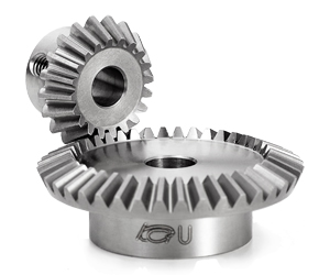
1. Tooth Geometry: Bevel gears have teeth cut on the cone-shaped surface of the gears, whereas other types of gears, such as spur gears and helical gears, have teeth cut on cylindrical surfaces. The tooth geometry of bevel gears allows them to accommodate intersecting shafts and transmit rotational motion at different angles.
2. Axis Orientation: Bevel gears have intersecting axes, meaning the shafts they are mounted on intersect each other. In contrast, other types of gears typically have parallel or skewed axes. The intersecting axis of bevel gears allows for changes in direction and allows for power transmission between shafts that are not in a straight line.
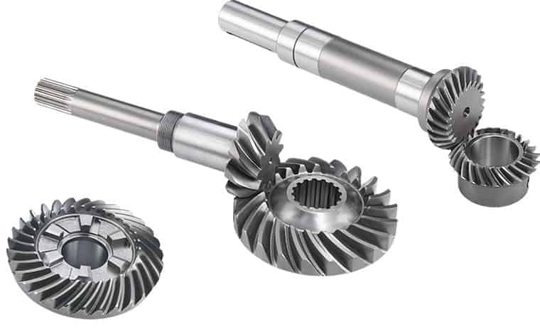
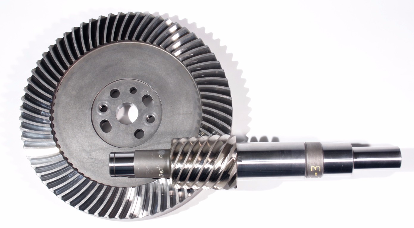
3. Types of Bevel Gears: Bevel gears come in different variations, including straight bevel gears, spiral bevel gears, and hypoid bevel gears. Straight bevel gears have straight-cut teeth and intersect at a 90-degree angle. Spiral bevel gears have curved teeth that are gradually cut along the gear surface, providing smoother engagement and reduced noise. Hypoid bevel gears have offset axes and are used when the intersecting shafts are non-parallel. Other types of gears, such as spur gears and helical gears, also have their own variations but do not typically involve intersecting axes.
4. Direction of Motion: Bevel gears can change the direction of rotational motion between intersecting shafts. Depending on the orientation of the gears, the direction of rotation can be reversed. This capability makes bevel gears suitable for applications where changes in direction are required. In contrast, other gears, such as spur gears and helical gears, transmit motion in a specific direction along parallel or skewed axes.
5. Load Distribution: Bevel gears distribute loads differently compared to other gears. Due to the conical shape of the gears, the contact area between the teeth changes as the gears rotate. This can result in varying load distribution along the gear teeth. Other gears, such as spur gears and helical gears, have a consistent load distribution along their teeth due to their cylindrical shape.
6. Applications: Bevel gears are commonly used in applications where changes in direction or speed of rotational motion are required, such as automotive differentials, marine propulsion systems, and power transmission systems. Other types of gears, such as spur gears and helical gears, are more commonly used in applications where parallel or skewed shafts are involved and changes in direction are not necessary.
While bevel gears have their unique characteristics, it’s important to note that different types of gears have their own advantages and applications. The selection of the appropriate gear type depends on factors such as the application requirements, operating conditions, space limitations, and load considerations.
In summary, bevel gears differ from other types of gears in terms of tooth geometry, axis orientation, types of variations available, direction of motion, load distribution, and applications. Their ability to accommodate intersecting shafts and change the direction of rotational motion makes them suitable for specific applications where other types of gears may not be as effective.


editor by Dream 2024-04-26

Recent Comments